

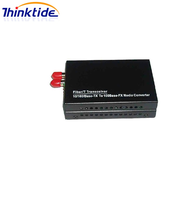
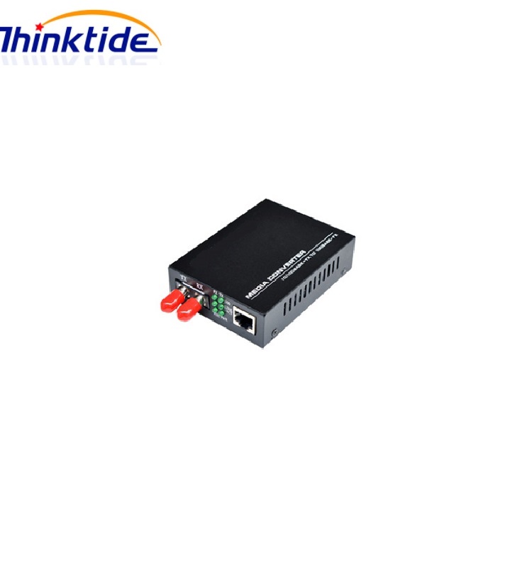
General Description
The media converter transform the transmission media of Ethernet signal from CAT5 to optical fiber. it can extend the transmission distance to several kilometer or hundred kilometer.
Using media converter is a economical solution to achieve long distance transmission base on current status.
Features
1. standard: In conformity to IEEE 802.3 10 Base-T standard.
In conformity to IEEE 802.3u 100 Base-TX/FX standard.
2. Built in 128Kb RAM for data buffer.
3. Back pressure flow control for full duplex
IEEE802.3 X and half duplex.
4. Automatic identification of MDI/MDI-X cross line.
5. Forward 1600 bytes packets for management. Can also reach 9k bytes (optional, Must inform us ahead).
6. Supports link fault pass through function.
7. Supports far end fault function.
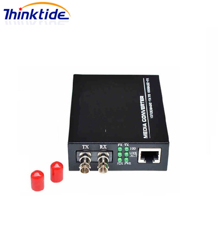
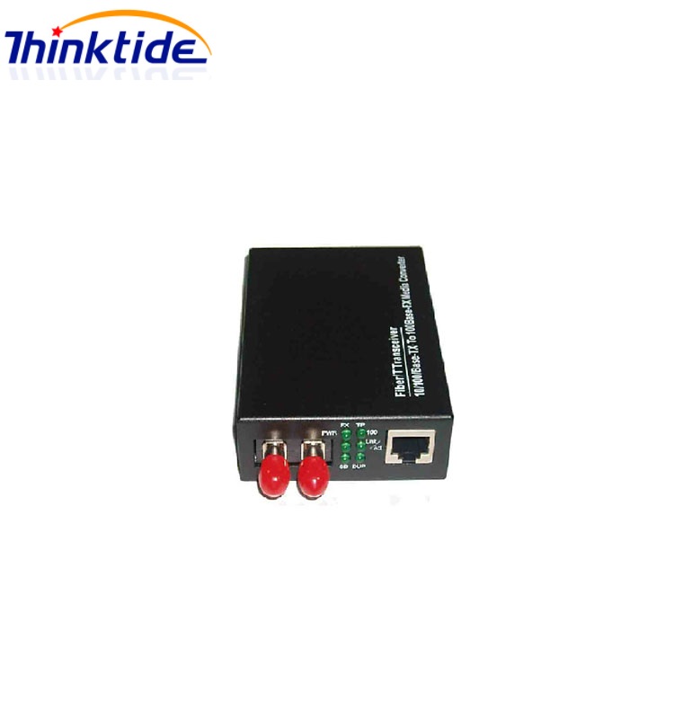
8. Fiber connector:Choice from SC,ST,FC or LC connector for multimode and single mode.
9. Built in a watchdog timer to monitor internal switch error.
10. LED display for link/activity,full/half,10M/100M.
11.Transmission distance can reach 2km for multimode and 120KM for single mode.
12.Support 4KV lighting protection(external power supply,Optional).
13.Can be rack mounted in 2U 14 slots chassis(external power supply).
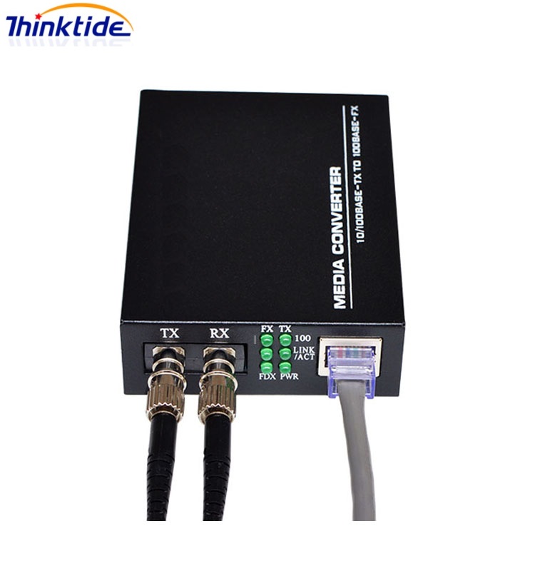
LED Function Description
LED indicator lamps serve as device monitoring and trouble display.
|
LED indicator lamp |
Status |
Explanation |
|
FX Link/Act |
On |
Connection status display for fiber link. “ON” indicates that Fiber link is in correct connection. |
|
Blink |
Active status display of fiber link “Blink” indicates packet goes through Fx end. |
|
|
TP Link/Act |
On |
Connection status display for electric link. “ON” indicates that electric link is in correct connection. |
|
Blink |
Active status display of electric link “Blink” indicates packet goes through Tx end. |
|
|
DUP |
On |
Transceiver works in the full duplex mode. |
|
Off |
Transceiver works in the half duplex mode. |
|
|
PWR |
On |
Power is on and normal. |
|
SD |
On |
Fiber signal is detected. |
|
100 |
On |
Transfer rate of electric interface is 100Mbps. |
|
Off |
Rate of electric interface is 10Mbps |
Table 3.1 Explanation for LED indicator lamp
Transmission characteristics of single and dual fiber transceiver
|
Dual fiber |
Interface |
Wavelength(nm) |
Transmitting optical power (dBm) |
Receving sensitivity(dBm) |
Transimission distance(km) |
Loss allowed(dBm) |
|
SM |
ST/SC/FC |
1310 |
-13 ~ -4 |
-33 |
20 |
19 |
|
SM |
SC |
1310 |
-8 ~ -3 |
-35 |
40 |
27 |
|
SM |
SC |
1310 |
-5 ~ 0 |
-36 |
60 |
34 |
|
SM |
SC |
1550 |
-8 ~ -3 |
-35 |
80 |
27 |
|
SM |
SC |
1550 |
-5 ~ 0 |
-36 |
100 |
31 |
|
SM |
SC |
1550 |
-2 ~ 3 |
-37 |
120 |
35 |
|
|
||||||
|
Single fiber |
Interface |
Wavelength(nm) |
Transmitting optical power (dBm) |
Receving sensitivity(dBm) |
Transimission distance(km) |
Loss allowed(dBm) |
|
SM |
SC |
1310/1550 |
-13 ~ -6 |
-30 |
20 |
Standard loss:1310nm 0.4/km 1550nm 0.25/km |
|
SM |
SC |
1310/1550 |
-8 ~ -3 |
-35 |
30 |
|
|
SM |
SC |
1310/1550 |
-6 ~ 0 |
-36 |
40~60 |
|
|
SM |
SC |
1310/1550 |
-3 ~ 3 |
-37 |
60~80 |
|
Table 3.2 Transmission characteristics of single and dual fiber transceiver
Table4.1 parameter
|
|
10/100M Singlemode Media converter |
|
Cable |
SM fiber/twist pair |
|
Operation Mode |
full duplex mode or half duplex mode |
|
Connector |
One UTP RJ-45connector,oneSC/ST/FC or one LC connector |
|
Power Supply |
outside: 5V DC 1A built-in: 110-265V AC or 48VDC or 12VDC(optional) |
|
Data Buffer |
128Kb |
|
Environmental temperature |
0~60 degrees |
|
Transfer Fiber |
single mode: 8.3/125, 8.7/125, 9/125 or 10/125 μm |
|
Raltive Humidity |
5%-90% |
|
Size |
94mm x 71mm x 26mm (Power external type) 150mm x 110mm x 26mm(Power internal type) |
 XPON Passive Optical Network
 snowthinktides
 0755-83068027
 sales@thinktides.com